Configure Bolt Pads
Bolt pads are specific to Decoupled Thermal Flexure analyses. They are not available in Compliant Mechanism scenes.
Use this guide to adjust bolt pad properties after they have been created -- either by STEP auto-detection or manual placement. Bolt pads are input preserves with additional geometry metadata that tells the solver where mounting holes are located and how they interact with the structure.
Steps
1. Select a bolt pad
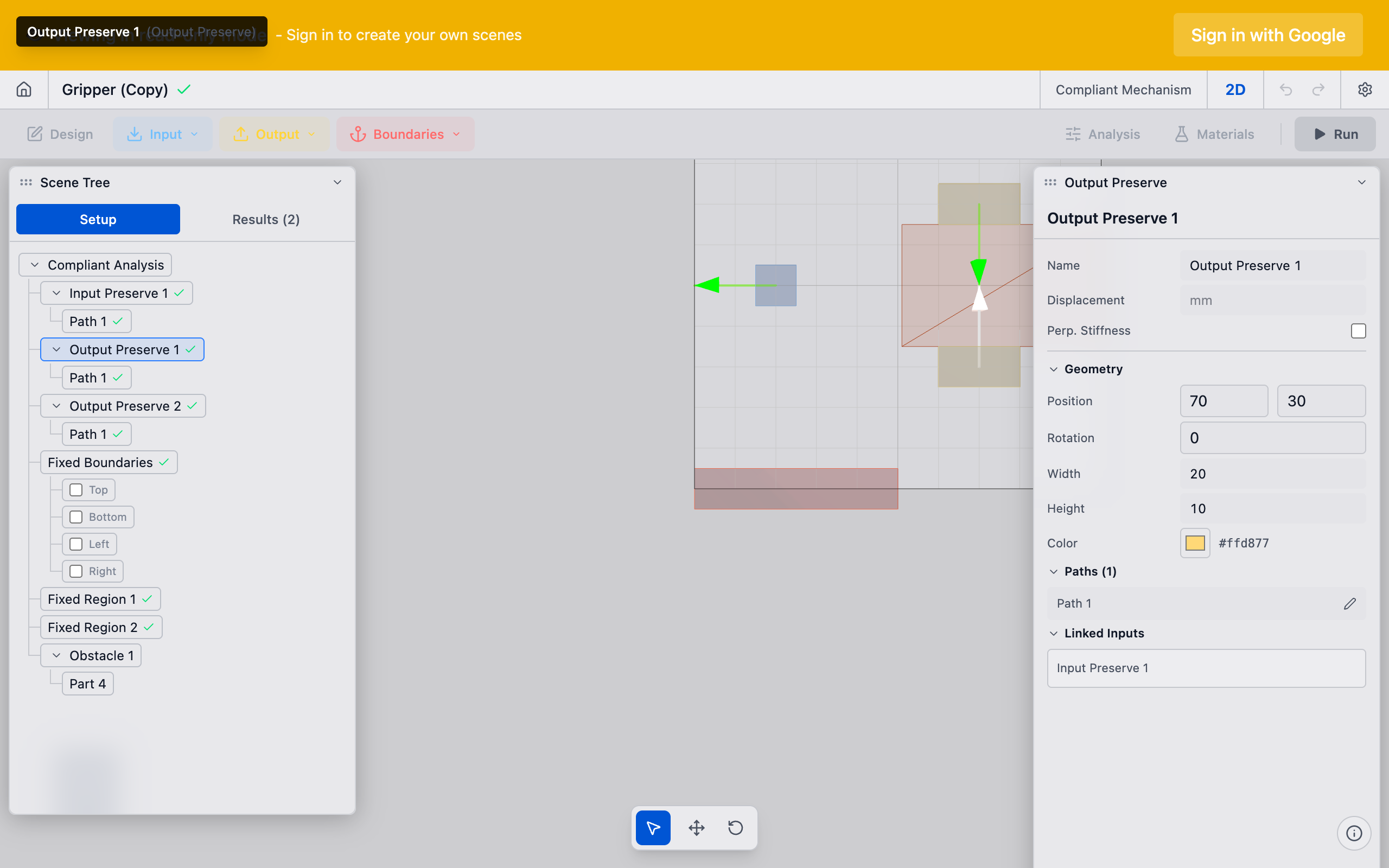
In the sidebar under Input Preserves, click the bolt pad you want to configure (e.g., "Bolt A"). The Properties panel loads its settings.

2. Adjust the bolt geometry
The bolt pad geometry defines the rectangular region around the bolt hole:
- Center X / Center Y: The center of the bolt hole in millimeters. For auto-detected bolts, these values come from the STEP geometry. Adjust if the auto-detection was slightly off.
- Width / Height: The pad extent around the hole. This should cover the material annulus that transfers load -- typically 2--3x the bolt hole diameter.
The solver assigns these nodes as preserved (kept solid) during optimization. Material in the bolt pad region is never removed.
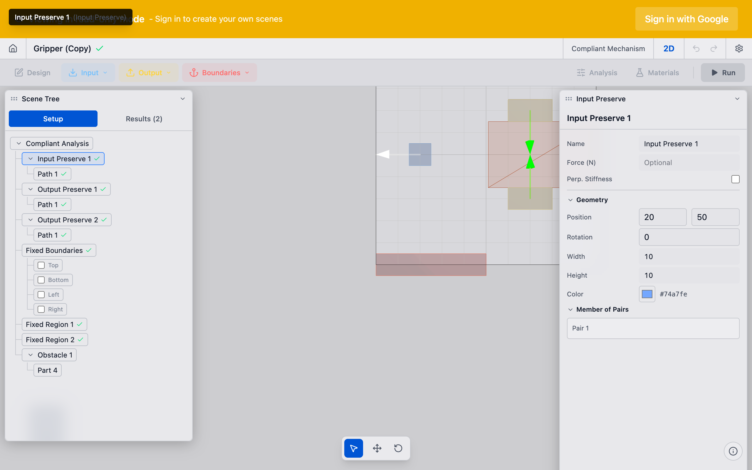
3. Set the input path direction
Each bolt pad needs a path that defines how force or displacement is applied:
- For compliant mechanisms: Set the path direction to match the applied force direction at that bolt location.
- For thermal flexures: Set the path to the expected thermal displacement direction. This is the direction the bolt moves due to thermal contraction of the substrate.
In a typical thermal flexure with a cooling plate, bolts near the corners displace radially inward toward the plate center. Set each bolt's path direction to point from the bolt toward the center of thermal contraction.
4. Configure bolt roles (thermal flexure only)
In Decoupled Thermal Flexure analyses, bolt pads can have different roles:
- Input bolt pads: Move with thermal displacement. These are standard input preserves with thermal directions.
- Output bolt pads (
role: output): Pinned mount points that are fixed in place. The solver treats these as zero-displacement boundary conditions. - Fixed bolt pads: Additional fixed points beyond the output mounts.
Ensure each bolt has the correct role for your physical configuration. The output bolt pads are where the mechanism is mounted to the optical bench or reference frame. The input bolt pads are where the cooling plate pushes.
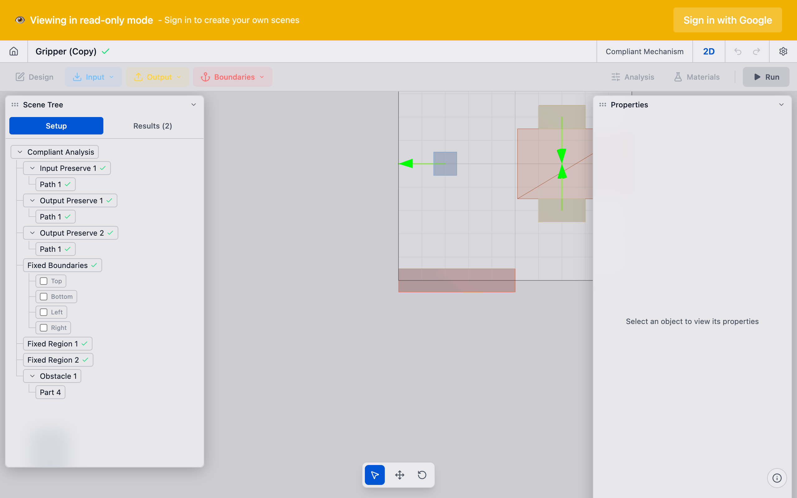
5. Verify all pads
Review all bolt pads in the viewport. Each pad should:
- Be positioned at the correct bolt center
- Have a pad size that captures the load transfer region
- Show the correct direction arrow (for thermal displacement or applied force)
- Have no overlap with adjacent pads or the domain boundary
Tips
- Pad size matters: If the pad is too small, the solver may not have enough constrained nodes to properly anchor the mechanism. If it is too large, you waste design domain area on forced-solid material.
- Thermal direction accuracy: For thermal flexures, the accuracy of the thermal displacement directions directly affects the quality of the optimized topology. Use the FEniCSx thermal stage results or manual calculations to determine the correct directions.
- Auto-detected geometry: After STEP import, bolt pad positions are rounded to 0.1 mm precision. Verify against your CAD model if sub-millimeter accuracy matters.
- Renaming: Double-click a bolt pad name in the sidebar to rename it. Use a consistent naming scheme (Bolt A, Bolt B, ...) that matches your mechanical drawing callouts.
What to do next
- Create preserve pairs to link bolt pads to the output preserve
- Run the analysis to generate the optimized topology
- Interpret results to evaluate the solver output