Add an Output Preserve
Use this guide to define where your mechanism should produce motion or deformation. The output preserve is the target -- the optimizer designs material topology that transfers input forces to achieve the output motion you specify here.
Steps
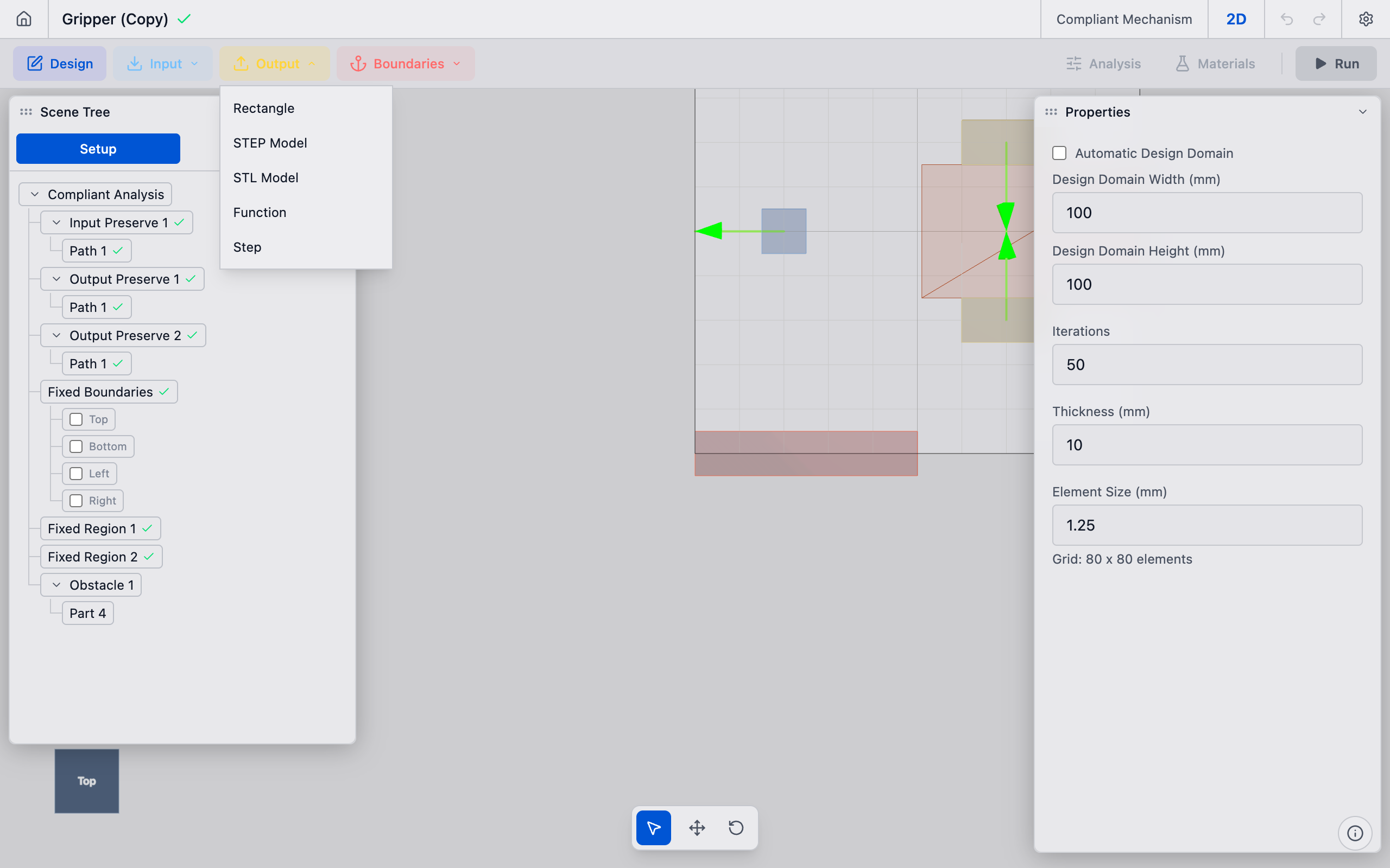
1. Create the output preserve
In the toolbar, click the Output dropdown button. Select Rectangle from the menu (or STEP Model / STL Model if importing geometry).
A new output preserve is created and appears in the Output Preserves section of the sidebar.
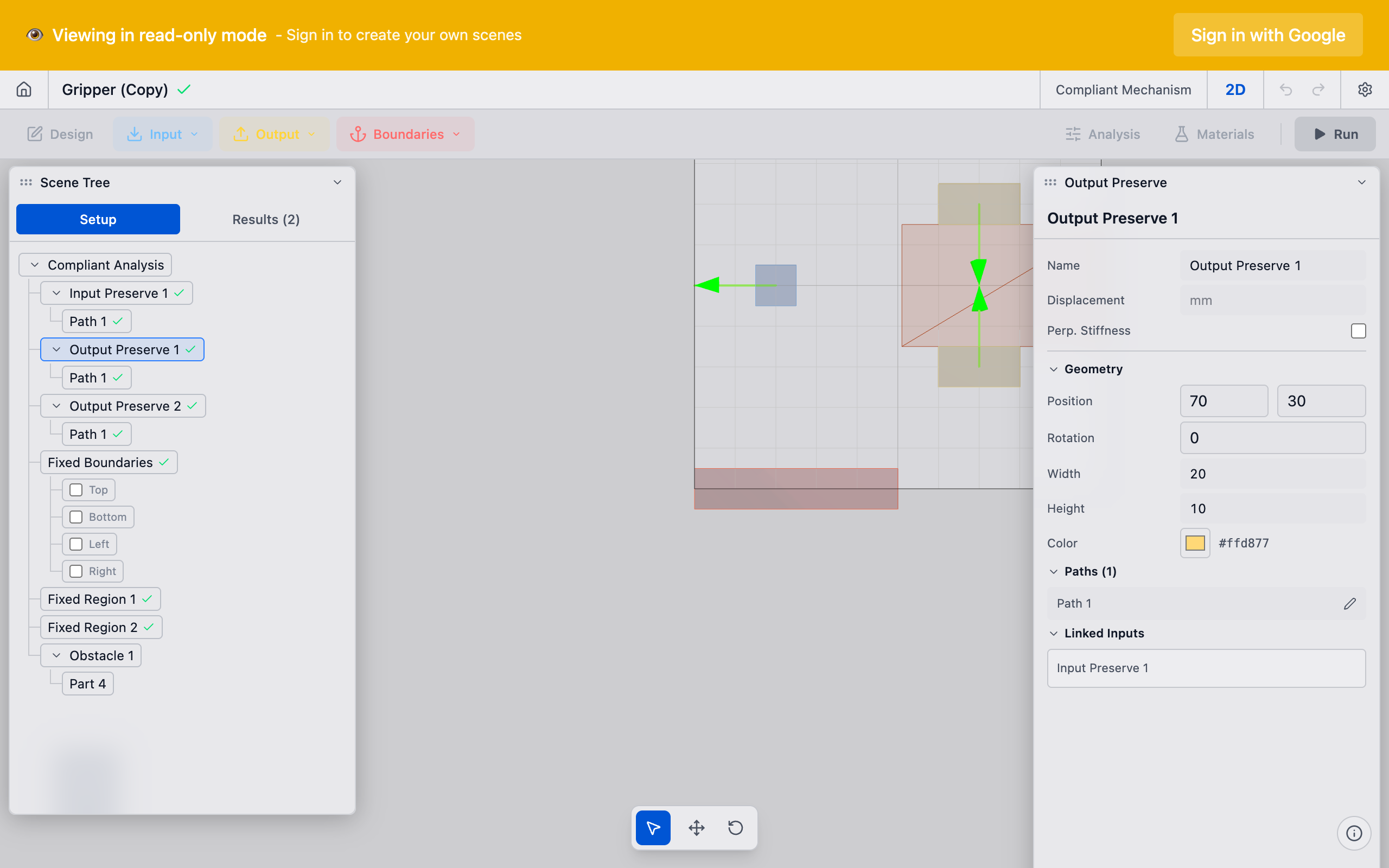
2. Position the part
Select the preserve in the sidebar. In the Properties panel, set the part position and dimensions:
- Position X / Y: Where the mechanism should produce output motion.
- Width / Height: Size of the output region.
For a force inverter, the output might be on the opposite side of the domain from the input. For a displacement amplifier, the output might be adjacent to the input but oriented differently.
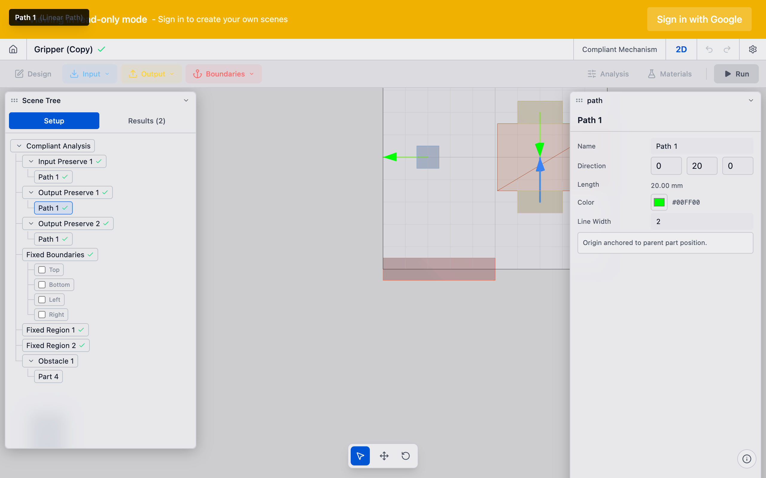
3. Configure the output path
In the Path section, define the desired output motion:
- Linear path: Direction and magnitude of the desired output displacement. A negative direction (relative to the input) creates an inverter mechanism.
- Rotational path: For mechanisms that should produce rotation at the output.
You can add multiple paths to a single output preserve for complex motion patterns (e.g., combined translation and rotation). Use the add path button within the output preserve to create additional paths.
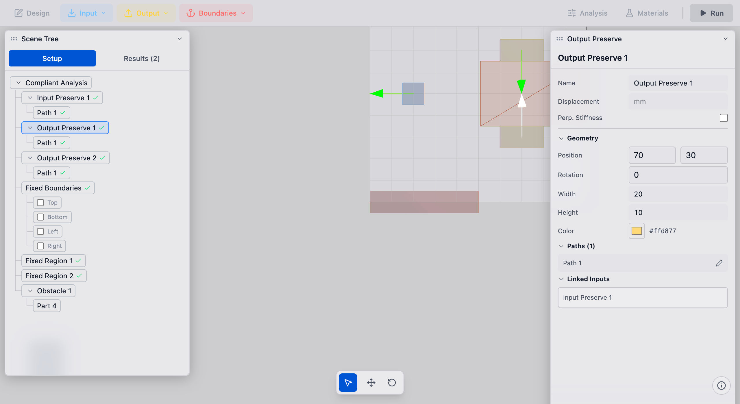
4. Verify directionality
In the viewport, the output preserve shows an arrow indicating the desired output direction. Confirm it matches your design intent:
- Arrow pointing in the same direction as the input = displacement amplifier or force transmitter
- Arrow pointing in the opposite direction = inverter or gripper
Tips
- Mechanical advantage: The ratio of output to input displacement is controlled by the Mechanical Advantage (J)* setting in Analysis Settings. A value of -1.0 means the output should displace the same amount as the input but in the opposite direction (inverter). Positive values create same-direction motion.
- Output stiffness: If you need the output to push against a load (not just move freely), the Max Characteristic Stiffness (K_p_max) setting on the pair controls how stiff the output point is. Higher values make the optimizer prioritize force transmission; lower values prioritize displacement.
- Single output: Most compliant mechanism problems have one output preserve. For multi-output mechanisms, create multiple output preserves and link each to the input through separate pairs.
- Deformation functions: For advanced use cases where the output is a distributed deformation pattern (not a point displacement), use the Output Function or Output Step preserve types from the Output dropdown.
What to do next
- Create a preserve pair to link this output to an input preserve
- Configure volume fraction before running the solver
- Run the analysis to generate the optimized topology