Add an Input Preserve
Use this guide to define where forces or displacements are applied to your mechanism. An input preserve consists of a part (the geometry where force is applied) and a path (the direction and magnitude of the input action).
Steps
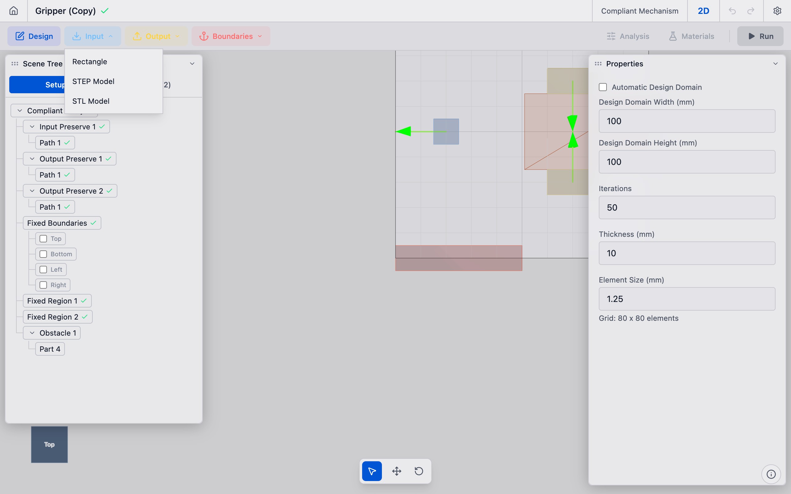
1. Open the creation dropdown
In the toolbar, click the Input dropdown button. Select Rectangle from the menu (or STEP Model / STL Model if importing geometry).
A new input preserve is created with a default rectangular part and added to the analysis. It appears in the Input Preserves section of the sidebar.
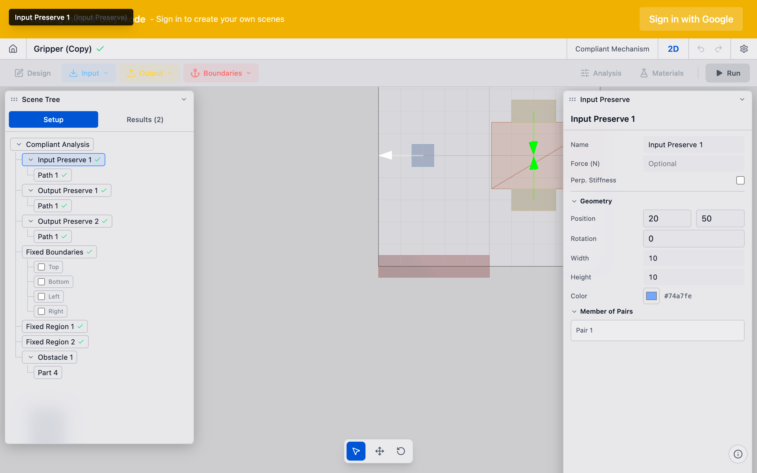
2. Position the part
Select the new preserve in the sidebar. The Properties panel shows the part properties:
- Position X / Y: Center of the input region in millimeters.
- Width / Height: Extent of the input region.
Place the part where the external force acts on your mechanism. For a bolt pad, position it at the bolt center. For a direct force input, position it where the actuator contacts the mechanism.
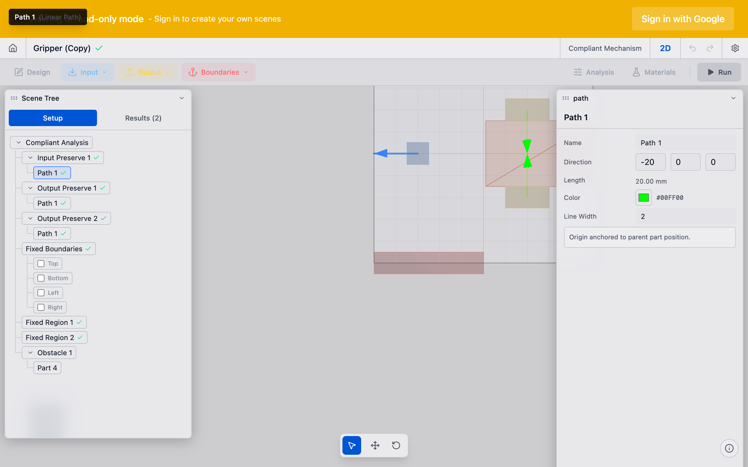
3. Configure the path
Scroll to the Path section in the Properties panel. The path defines the input action:
- Linear path: Specify a direction vector (X, Y, Z components). The magnitude represents the applied displacement or force direction.
- Rotational path: Specify a rotation axis, angle in degrees, and center offset.
For most compliant mechanism problems, use a linear path pointing in the direction you want to push or pull the mechanism.
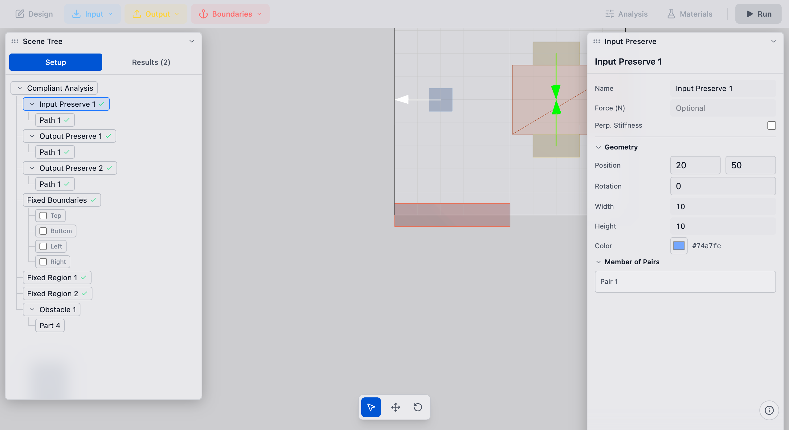
4. Verify in the viewport
The input preserve renders as a colored marker in the viewport with an arrow indicating the path direction. Confirm the arrow points in the correct direction and the marker covers the intended input region.
5. Link to a pair (if needed)
For the solver to use this input, it must be part of a preserve pair that couples it to an output preserve. See Create Pairs for details.
Tips
- Multiple inputs: You can add several input preserves for mechanisms with multiple input points. Each one needs its own path and must be linked to an output through a pair.
- Source type: Preserves created from STEP bolt hole detection have
source: boltset automatically. Manually created preserves usesource: manualand can be freely positioned. - Naming: Rename the preserve to something descriptive (e.g., "Actuator Input" or "Bolt A") by right-clicking it in the sidebar and selecting Rename.
- Part size: The part should cover enough area for the solver mesh to capture the load distribution. A single-element input region can cause stress concentrations. Use a width/height of at least 2--3x the element size.
What to do next
- Add an output preserve to define where the mechanism should produce motion
- Create a preserve pair to link input and output preserves
- Add a fixed preserve to anchor the mechanism