What is deFlex?
deFlex is a browser-based generative design tool that helps engineers create compliant mechanisms using AI-driven design optimization. You define the design space, specify where the mechanism should be stiff, where it should flex, and where forces act — then the solver computes an optimized material layout that meets your requirements.
Everything runs in the browser. There is nothing to install. You open a URL, import your geometry, set up the problem, and run the solver. Results stream back as the optimization progresses, so you can watch the design take shape in real time.
Who is deFlex for?
deFlex is built for anyone who needs to design parts that flex predictably under load:
- Mechanical engineers designing flexures, snap fits, compliant grippers, or living hinges
- Product designers exploring form-driven mechanisms that replace multi-part assemblies with a single printed part
- Researchers studying computational design, metamaterials, or mechanism synthesis
- Students learning about structural design in a visual, interactive environment
You do not need prior experience with design optimization or structural analysis. deFlex handles the simulation, the math, and the solver configuration behind the scenes. Your job is to describe the problem — the tool finds the solution.
What is a compliant mechanism?
A traditional mechanism uses rigid links connected by joints — hinges, pins, sliders — to transmit motion and force. A compliant mechanism achieves the same thing through controlled elastic deformation of a single monolithic part. Instead of separate moving pieces, the part itself bends in designed-in ways.
Compliant mechanisms are everywhere once you start looking:
- Binder clips flex open and spring shut because of their geometry, not because they contain a hinge
- Shampoo bottle caps use a living hinge — a thin strip of plastic that bends thousands of times without breaking
- MEMS accelerometers in your phone rely on microscale flexures to detect motion
- Surgical instruments use compliant jaws that grip tissue without discrete pivot points
The advantages over traditional mechanisms are significant: no assembly, no wear at joints, no lubrication, no backlash, and the part can often be manufactured in a single operation (3D printing, injection molding, CNC milling, or sheet metal fabrication).
The challenge is designing them. Unlike a pin joint where the rotation axis is obvious, a compliant mechanism's behavior emerges from the complex interplay between its geometry, material properties, and boundary conditions. This is where deFlex's design engine comes in.
How does deFlex design mechanisms?
deFlex uses an AI-driven design optimization engine that explores the design space and determines where to place material to achieve the best possible performance. You describe the problem; the solver figures out the solution.
In deFlex, the process works like this:
- You define the design domain — the outer boundary of the region where material can exist. This might be a rectangular plate, an imported STEP file, or a custom 2D shape.
- You mark preserves — regions that must remain solid. Bolt holes, mounting surfaces, and contact pads are typical preserves. The solver will not remove material from these areas.
- You set boundary conditions — where the part is fixed (bolted down) and where forces or displacements are applied.
- You specify the design objective — for compliant mechanisms, this is typically maximizing the output displacement at a target point for a given input force, subject to a volume constraint.
- The solver iterates — the engine runs tens to hundreds of iterations, progressively refining the material layout. Material concentrates along the most effective load paths, and voids open up where material is not needed.
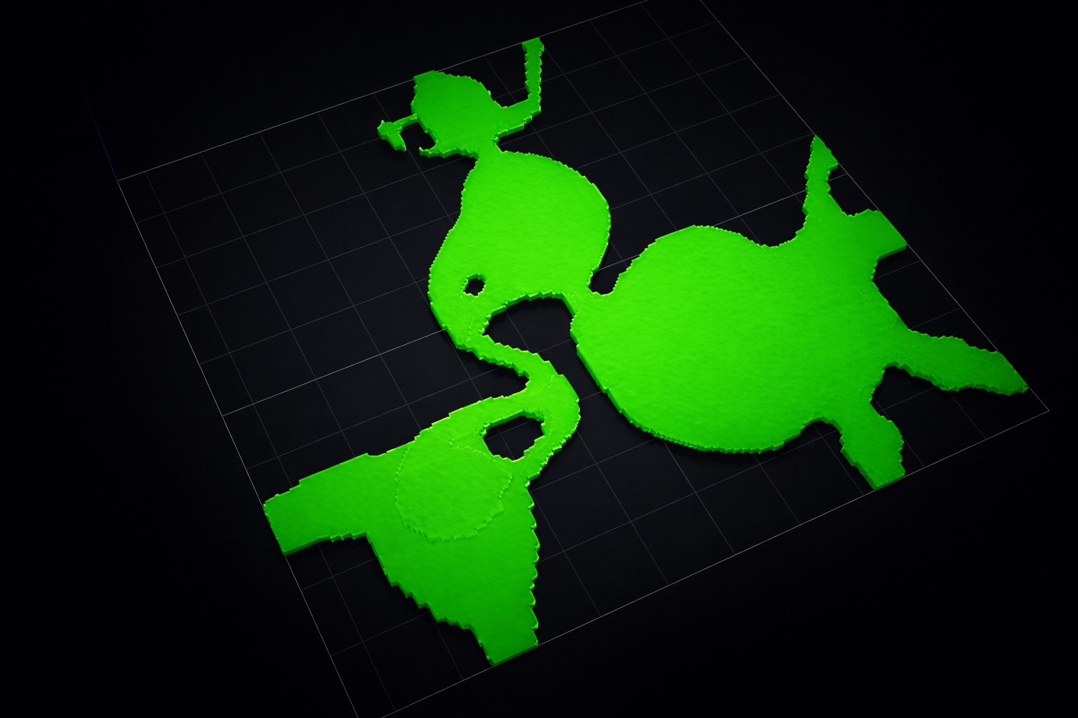
The result is a design that is structurally efficient and often surprising — organic-looking shapes with thin flexural members connecting stiff regions, resembling something between a skeleton and a tree branch.
The solver finds a design that is optimal for the specific loading and boundary conditions you define. If the real-world conditions differ significantly from what you modeled, the design may not perform as expected. Accurate problem setup is the most important step.
Key capabilities
Import and create geometry
deFlex supports STEP file import for 2D cross-sections. You can import existing CAD geometry as the starting design domain, or create simple shapes (rectangles, plates with holes) directly in the interface. Bolt holes and mounting features are automatically detected during import.
Define preserves and boundary conditions
Preserves are regions you mark as "keep solid." They define the functional surfaces of your part — where bolts go through, where the part contacts other components, and where forces are applied. You place preserves visually in the 3D viewport or specify them in the properties panel.
Boundary conditions include:
- Fixed supports — nodes that cannot move (e.g., bolted mounting points)
- Input forces — where and in what direction force is applied to the mechanism
- Output targets — where you want the mechanism to produce displacement
Run the solver
The design solver runs server-side — your browser sends the problem definition to the backend, and solver workers handle the computation. This means you do not need a powerful local machine. A laptop with a modern browser is sufficient.
Solver progress is streamed back to the browser. You can watch the design evolve iteration by iteration, see the design performance converge, and monitor volume fraction in real time.
View and export results
Once the solver finishes, you can:
- Inspect the optimized design in the 3D viewport with adjustable density thresholds
- Review convergence plots (performance vs. iteration, volume fraction vs. iteration)
- Export the result for downstream CAD refinement or manufacturing
Decoupled thermal flexure optimization
For thermal applications — designing flexures that accommodate thermal expansion — deFlex provides a decoupled solver workflow. You define bolt pads with thermal displacement directions, and the solver generates a compliant flexure that allows thermal motion while maintaining structural stiffness where needed. This is particularly useful for optical mounts, precision instruments, and electronic packaging.
How deFlex fits into your workflow
deFlex is not a replacement for your full CAD package. It is a concept generation tool. The typical workflow looks like this:
- Define the problem in deFlex — import the envelope geometry, place preserves, set boundary conditions
- Run design optimization — let the solver find an efficient material layout
- Export the result — take the optimized design back to your CAD tool
- Refine the geometry — smooth curves, add fillets, adjust for manufacturing constraints
- Validate — run a full structural analysis in your simulation tool to confirm performance
Design optimization gives you a strong starting point. It tells you where material should be and where it should not be. The engineering judgment of interpreting and refining that result is still yours.
The quality of the output depends entirely on the quality of the input. Spend time getting your preserves, boundary conditions, and volume fraction right before running the solver. A well-defined problem almost always produces a useful result on the first run.