Create a Parametric Plate
Use this guide when you want to define a simple rectangular design domain without importing CAD geometry. This is the fastest way to start a new optimization problem.
When to use a parametric plate
A parametric plate is appropriate when:
- You are exploring concepts and do not yet have finalized geometry
- Your design domain is genuinely rectangular (a flat mounting plate, a bracket blank)
- You want to iterate quickly on preserve placement and solver settings before committing to imported geometry
If you already have a CAD model, see Import a STEP File instead.
Steps
1. Create a new scene
From the home page, click New Scene. Select your analysis type (Compliant Mechanism or Decoupled Thermal Flexure) and dimension (2D or 3D). The scene opens with a default 100 x 100 mm design domain.
2. Open Design Settings
Click the Design toggle in the toolbar to open the Design Settings panel. This panel controls the design domain geometry and solver mesh settings.
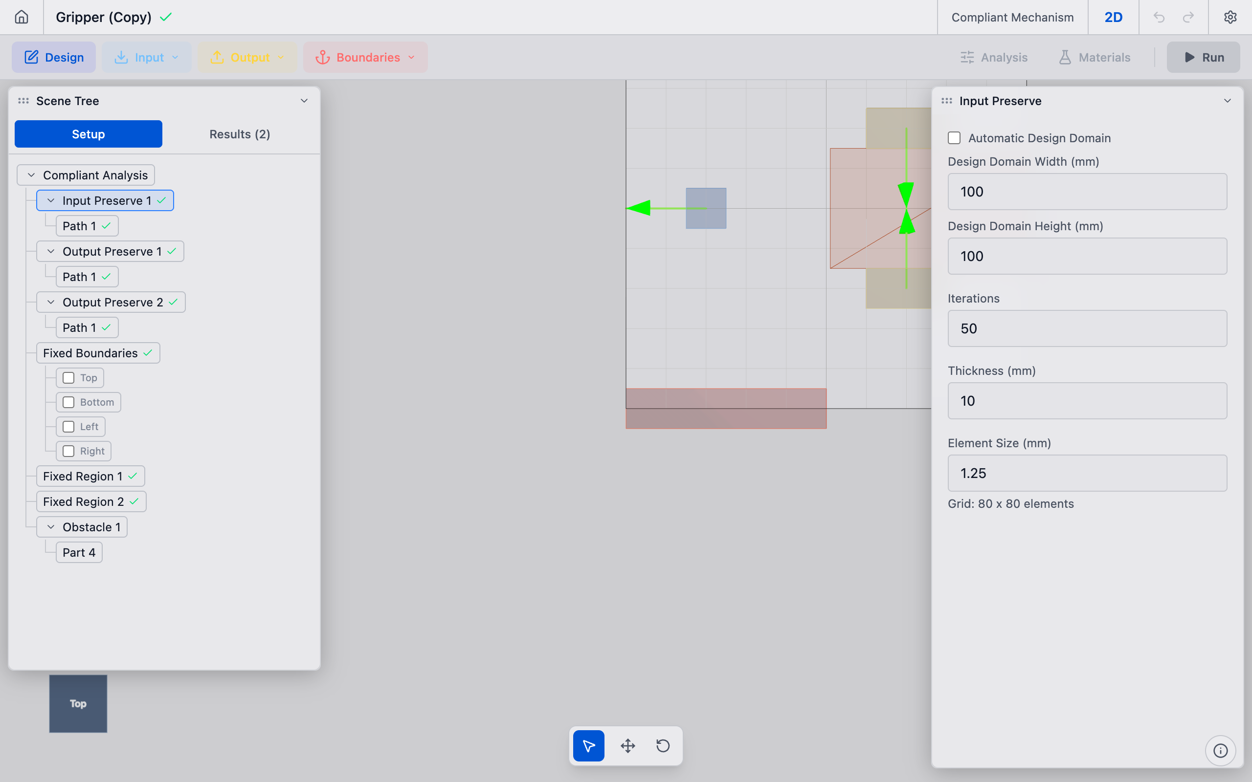
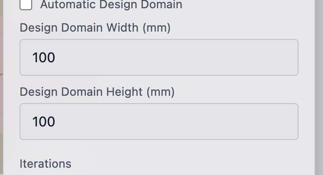
3. Set domain dimensions
Under Domain Settings, ensure Automatic Design Domain is unchecked (manual mode). Enter your desired dimensions:
- Width (mm): The horizontal extent of the plate.
- Height (mm): The vertical extent of the plate.
For 3D scenes, a Depth (mm) field also appears.
The viewport updates immediately to show the resized domain.
4. Use automatic domain mode (optional)
If you prefer, check Automatic Design Domain. In this mode, deFlex computes the domain boundary from the positions of your bolt pads and output preserves, plus a configurable padding percentage. This is useful when you have placed preserves first and want the domain to fit snugly around them.
Adjust the Padding slider (10%--50%) to control how much extra space surrounds the preserve positions.
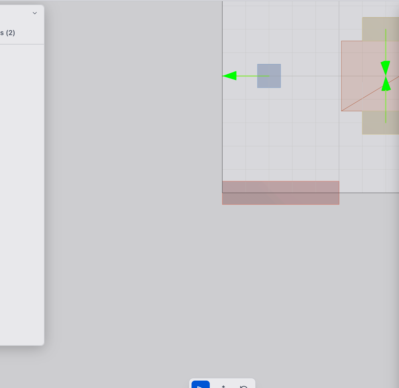
5. Verify in the viewport
The rectangular domain appears as a semi-transparent outline in the 3D viewport. Confirm the dimensions match your intent. The Grid readout in Design Settings shows the resulting element count (e.g., "50 x 50 elements"), which gives you a sense of the mesh resolution.

Tips
- Typical plate sizes: Precision instrument mounts are often 200--400 mm. Start with a size that matches your real-world envelope.
- Aspect ratio: Avoid extreme aspect ratios (e.g., 10:1). The solver works best when the domain is roughly square or moderately rectangular.
- Thickness: For 2D analyses, set the Thickness field in Design Settings to match the physical plate thickness. This affects stiffness calculations. The default is 1 mm.
- Coordinate system: deFlex uses a Z-up coordinate system. Width is along X, height is along Y.
What to do next
After creating your plate:
- Add bolt holes to define mounting positions
- Add input preserves where forces or thermal displacements act
- Adjust mesh resolution via Choose Mesh Resolution